IT and UPS load
Power-electronic server, rectifier and power-supply behaviour with voltage sensitivity and recovery settings.
Large-load power-system models
Represent the transmission or distribution interconnection, redundant transformer paths, medium-voltage buses, IT and cooling loads, standby generation, BESS and reactive controls in one electrical case.
Model the campus
A useful interconnection model must explain how the facility is connected, how the load is divided, which components can provide voltage or reactive support, and how the campus behaves during grid disturbances.
HV Power Flow keeps that architecture visible and ties it to the same steady-state, sequence and dynamic records used for utility exchange.
Data-center load behaviour
Dynamic studies become more meaningful when electronic load, rotating equipment and controls are not treated as one instantaneous step.
Power-electronic server, rectifier and power-supply behaviour with voltage sensitivity and recovery settings.
Motor B-style fan behaviour or the cooling portion of a composite load representation.
Motor C-style load behaviour for circulating and cooling-water pump systems.
Motor A-style dynamics for compressor-driven cooling equipment where applicable.
Gas-turbine machine, exciter and governor characteristics for on-site generation scenarios.
Zero-MW steady-state operation with reactive support and active-power response during dynamic events.
Event-driven studies
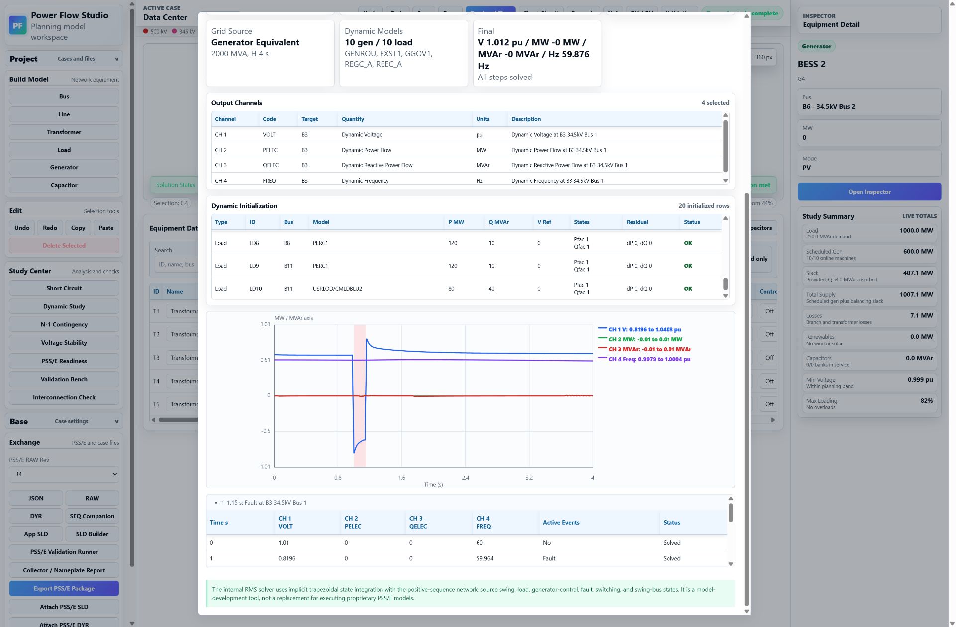
Build a timed event table with bus or equipment faults, switching actions, and source voltage or frequency disturbances. Measure voltage, frequency, MW and MVAr at another bus or item while the model advances through the event sequence.
Large-jurisdiction workflow
Regions such as ERCOT publish specific processes and modelling resources for large loads. HV Power Flow helps a project team assemble the network, load composition, sequence values and dynamic records before licensed study validation.
| Model package area | Project data to prepare | HV Power Flow output |
|---|---|---|
| Steady state | POI topology, transformer and line impedances, load blocks, generation and controls | PSS/E-compatible RAW network case |
| Sequence data | Utility strength, line and transformer sequence values, machine grounding and motor contribution | Sequence-data companion and completeness checks |
| Dynamic data | Load composition, ride-through, generator, BESS and plant-control parameters | Supported DYR records and ordered parameter review |
| Diagram | Terminal relationships, voltage levels, redundant paths and equipment identification | Saved app SLD and PSS/E SLD Builder workflow |
| Validation | Target PSS/E version, official base case and utility study assumptions | Readiness report and PSS/E validation runner |
HV Power Flow is not affiliated with or approved by ERCOT. Current ERCOT, transmission-provider, distribution-provider and utility requirements remain controlling.
Utility exchange
Export the data-center network to PSS/E RAW revision 34 or 35, include supported dynamic and sequence records, and give the reviewer the model architecture rather than only a spreadsheet or diagram.
Replace preliminary values with utility and manufacturer data, confirm the current study guide, and read the package back in the utility's target PSS/E environment. A qualified professional remains responsible for the engineering and submission.
Model the campus architecture, study its response and prepare the PSS/E exchange package in one workspace.